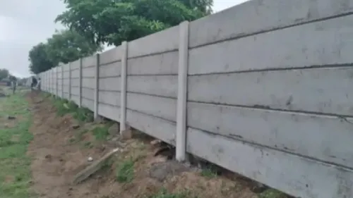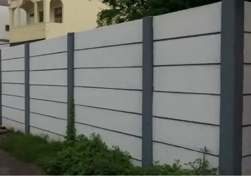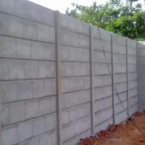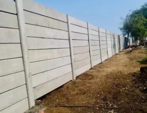
A durable precast wall depends on more than placing panels between posts: the line, foundation, lifting plan, temporary bracing, joints and drainage must work together. By the end, you will know how to prepare the site, erect the wall safely and inspect every connection before backfilling or handing over the property.
Key takeaways
- Set the wall line from a legal boundary survey, not an existing fence.
- Match foundation design to soil, drainage, slope and wall loads.
- Confirm delivery access, panel storage and lifting equipment before dispatch.
- Install posts and panels in sequence, then inspect joints, alignment and gates.
Survey the Site and Set Out the Wall Before Excavation
Fix the finished wall line from a legal boundary survey, not from an existing fence that may already be misplaced. Mark corner points, changes in direction, returns, gate openings and end points with durable stakes, then run a string line or total-station line between them.
Record each opening’s clear width and the centreline of every post.
- Locate a permanent benchmark and transfer the proposed top, base and post-seat levels along the route. Use a laser level or automatic level; do not follow ground contours by eye.
- Measure each bay and confirm that panel lengths fit between corners, returns, gates and closure sections. Small errors repeated across many bays can move the final wall significantly.
- Mark underground water, sewer, electricity, gas and telecommunications services from utility records and physical locating. Keep excavation outside the stated clearance zones or obtain written approval before digging.
- Walk the alignment for slopes, soft ground, standing water, drainage paths, trees, retaining edges, driveways and overhead wires. Check truck access, crane setup space and room for excavated soil.
- Recheck the set-out against the approved drawing, property boundary and gate swing. Photograph the marks and record offsets from fixed features before excavation removes them.
Do not start post holes until the line, levels, opening dimensions and site constraints are signed off. If the supporting foundation already exists, survey its line, level, anchor-bolt positions, bearing seats and grout pockets first; never force a panel to correct a surveying error.
Design and Build Foundations for the Actual Ground Conditions
A standard footing size is unsafe when soil or wind conditions change. Set post foundation dimensions from the wall height, post spacing, panel weight, wind exposure, soil bearing capacity and any retained soil. Loose fill, expansive clay and soft or waterlogged ground require a geotechnical review rather than a larger guess.
- Use deeper, wider foundations where bearing capacity is low, wall height increases, or exposed wind produces greater overturning. Reinforce each footing with the bar size, spacing and anchorage shown on the structural drawings; do not substitute leftover steel.
- Set embedment depth below the specified founding level and below any loose topsoil, erosion zone or slope edge. On sloping ground, step the foundations and keep every post plumb instead of burying posts to uneven depths.
- Treat groundwater as a design load and a construction hazard. Provide temporary dewatering, stable excavation support and concrete placement suited to wet conditions; never pour into flowing water without an engineered method.
- Use the specified concrete strength, place it without segregation, vibrate around reinforcement and keep it moist for the required curing period. Early loading can crack a footing before the wall is stable.
- Keep drainage separate from retaining design. A wall holding soil needs checks for lateral earth pressure, hydrostatic pressure, surcharge, sliding, overturning, bearing and overall slope stability, plus free-draining granular backfill, filter fabric and a designed outlet.
High wind sites also need temporary bracing sized for construction-stage wind, not just the completed wall. Remove braces only after permanent connections and any required roof or floor ties are complete.
Plan Delivery, Storage and Lifting Before Panels Arrive
Do not dispatch a panel until the truck route and unloading area have passed a site check. Confirm turning radius, overhead power lines, bridge and road limits, crane setup area, outrigger spread, firm ground and enough laydown space for the planned unloading sequence.
1. Survey the foundation before delivery. Record wall line and level, post or anchor-bolt locations, bearing-seat elevations, openings and grout-pocket condition. Correct errors before lifting; forcing a panel into position creates cracking and accumulated alignment defects.
2. Prepare an engineered lifting plan. Include each panel’s weight, centre of gravity, lifting inserts and their certified capacity, sling angles, dynamic effects, landing orientation, wind limit, crane radius and ground bearing beneath outriggers or crawler tracks. A crane rated above the panel weight can still fail at the working radius.
3. Assign a qualified crane operator, rigger, signalperson and erection crew. Establish one signal system, an exclusion zone, radio communication and a clear escape path. Require helmets, safety footwear, high-visibility clothing and fall protection where workers access elevated areas.
4. Lift only after the approved release strength is recorded in the shop drawings or erection plan. Early lifting can pull out inserts, break panel edges or cause cracks even when 28-day concrete strength later passes.
5. Store panels upright or in the approved orientation on firm, level dunnage at designed support points. Keep blocking vertically aligned between stacked units; never lay panels flat unless the approved method permits it. Use specified bearing pads and shims, not random packing.
Ask Trimurti Precast for the lifting points, release strength and storage diagram before the load leaves the plant.
Related products
 | Compound Walls Product Details: Minimum Order Quantity 200 Feet Material Concrete Wall Type Compound Wall Thickness 50 mm Built Type Prefab Material Grade M30 Plank... View product → |
 | Godown Walls Product Details: Material Concrete Built Type Prefab Build Thickness 2 - 4 inch Length 7 feet To fit the requirements of the patrons, we are engaged... View product → |
Install Posts and Panels in a Controlled Erection Sequence
Do not start lifting panels until the foundation survey passes its hold points: wall line, post centres, bearing-seat elevations, anchor locations, gate openings and grout pockets. Correct small errors with approved shims or connection hardware; forcing a panel into position transfers stress into the concrete.
1. Confirm the erection drawings, lifting points and specified sequence. Mark each post and panel position, including corners, returns, openings and closure locations.
2. Set the first post on its designed footing or anchor connection. Check plumb, line and elevation, then install temporary bracing before releasing the lifting equipment.
3. Place the next post, measure the clear panel opening, and complete panel insertion from the approved lifting position. Keep the panel seated on its designed bearing points; never use a crane to force a misaligned unit.
4. Continue post placement and panel insertion in short, controlled bays. Recheck line, plumb, joint width and top elevation after every panel because errors accumulate along a long wall.
5. Build corners and returns as shown on the drawings. Brace both wall directions, and install corner units or closure pours in the specified order so one leg does not restrain the other prematurely.
6. At an elevation change, use the designed stepped foundation and step the panels at their bearing seats. Do not bridge a change with an unsupported panel or cut a unit on site without engineering approval.
7. Complete bolts, welds, grout or other permanent connections before removing temporary bracing. Keep bracing in place until the approved connections and any required roof, floor or diaphragm ties can resist construction-stage wind and impact.
Complete Connections, Weatherproofing and Final Inspection
Keep every panel joint capable of carrying its intended load before applying sealant. Inspect welded plates, bolts, grout pockets, sleeves and cast-in closures; complete and document each connection before concealment. Install bearing pads and shims at the specified locations and areas, because concentrated bearing can crack or spall a panel edge.
Prepare panel joints by cleaning and drying the concrete, installing the specified backer material and bond breaker, then applying a compatible, movement-rated sealant at the designed joint width. A sealant bead does not replace structural connection or drainage. Coordinate flashing, end dams, coping, and wall-to-foundation transitions so water has a defined exit path.
Fit gate frames and posts to their designed foundations, checking hinge alignment, latch clearance and swing before permanent grouting. Seal penetrations with compatible sleeves, flashing and sealant; do not rely on a top-edge bead to stop water at pipes, cables or window interfaces. Place backfill in controlled lifts without striking panels.
A retaining application needs separate design for earth pressure, groundwater, surcharge, sliding, overturning and bearing; provide free-draining granular material and a designed outlet.
- Re-survey wall line, plumb, elevation, corners and gate openings.
- Check joints, connections, grout and sealant for gaps, cracks or incomplete work.
- Confirm drains discharge freely and backfill does not block outlets.
- Remove temporary bracing only after connections and grout have reached the specified condition.
- Record the inspection, then test gates and release the wall for use only when it is stable and safe.
Frequently asked questions
How should you set out a precast wall before excavation?
Use a legal boundary survey to establish the finished wall line. Mark corners, direction changes, returns, gate openings and endpoints with durable stakes, then check the line with string or a total station.
How do you design foundations for a precast wall?
Base the foundation on actual ground conditions, including soil, drainage, slope and wall loads. Check the required footing depth, width, reinforcement and concrete details before excavation.
What must you plan before precast wall panels arrive?
Confirm truck access, unloading space, a stable storage area and lifting equipment. Plan the erection route and keep panels supported in a way that prevents damage or unsafe handling.
What is the correct sequence for installing precast wall panels?
Install and align the posts first, verify spacing and plumb, then place panels in the planned sequence. Finish connections, joints, weatherproofing and gate interfaces before final inspection.
Related products
 | Boundary Walls Material Concrete Type Prestressed Color Grey Beam Size 6 x 6 Inches, 150x150 mm, 200 mm x 200 mm Size 6 feet Country of Origin Made in India we... View product → |
 | Compound Walls Product Details: Material RCC Built Type Prefab Build, Panel Build Plank Length 7 Ft Width 2 Inches Beams Size 6x6 Inches, 150x150 mm, 200 mm x 200... View product → |
 | Compound Walls Material Cement Type Boundary Wall Color White Size 8*10 Wall Height 8 to 10 feet Country of Origin Made in India we Trimurti Precast are the leading... View product → |
 | Boundary Walls Material Concrete Type Prestressed Color Grey Beam Size 6 x 6 Inches, 150x150 mm, 200 mm x 200 mm Size 6 feet Country of Origin Made in India we... View product → |