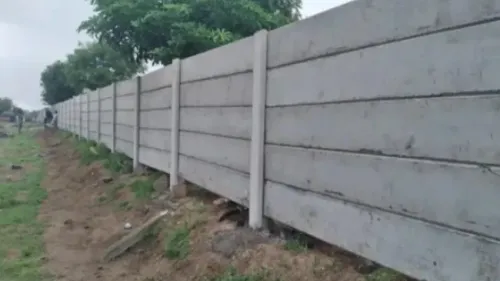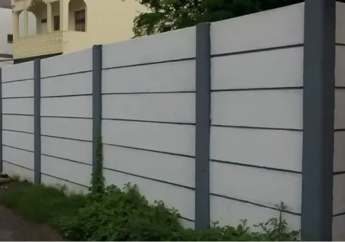
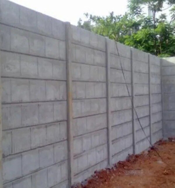
A compound wall is only as stable as the complete load path from its panel to the soil beneath its foundation. By the end, you will be able to distinguish genuine prestress benefits from unsupported strength claims and specify the panel, connections, posts and foundations using comparable design information.
Key takeaways
- Check how prestressing reduces tensile cracking under bending.
- Trace wind and impact forces through panels, posts, foundations and soil.
- Inspect joints, installation tolerances, soil conditions and drainage before choosing a system.
- Request tendon details, concrete strength, test records and installation tolerances from suppliers.
What prestressing changes inside a compound wall panel
A prestressed concrete panel carries built-in longitudinal compression before service loads arrive. During manufacture, prestressing steel tendons or wires are tensioned and anchored so their force transfers into the hardened concrete. When wind or impact bends the panel, that compression counteracts the tensile stress that would otherwise open cracks.
Ordinary reinforced-concrete panels rely on passive steel reinforcement after concrete has begun to crack, so prestressing can deliver greater bending capacity from a thinner section.
- Pretensioning stretches the steel on a casting bed before concrete is placed. After the concrete reaches the specified strength, the tendons are released and their contraction compresses the panel.
- Post-tensioning places ducts or tendons in the panel, then tensions and anchors them after the concrete has hardened.
Ordinary reinforced-concrete panel | Prestressed concrete panel Load response | Steel resists tension after cracking begins | Initial compression delays tensile cracking Panel size | More concrete may be needed for the same span | A thinner, lighter section can carry bending efficiently Production control | Reinforcement remains passive during casting | Tendon force, concrete strength and release timing must be controlled
The lighter panel reduces lifting and transport effort, but it leaves less tolerance for impact, poor support or erection errors. Prestressing does not make the panel crack-proof, and it cannot compensate for weak connections or inadequate support.
Its benefit is greatest when the panel spans between closely spaced, accurately aligned posts; increasing span raises bending demand rapidly.
How forces travel from the panel into the ground
A panel does not deliver wind or impact forces directly to the earth. The compound wall load path runs from the panel or infill through bearing and the panel-to-post connection, into post bending and shear, then through the footing or grade beam and finally into the soil.
Panel strength is one link, not the complete wall.
Assess the complete load path for:
- Post bending and shear, including post spacing and post embedment
- Footing or grade-beam width and depth for foundation stability
- Soil bearing pressure, settlement and loss of support
- Overturning, sliding and uplift
- Local concrete failure around each post socket
Prestress can delay cracking in the panel while the foundation fails first. An undersized footing, weak soil or short post embedment cannot resist the overturning moment created by wind, regardless of the panel’s compressive strength.
A solid wall also attracts different wind pressure from a porous fence, so site exposure, wall height and permeability belong in the calculation.
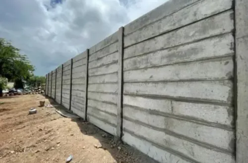
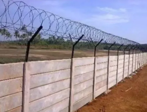
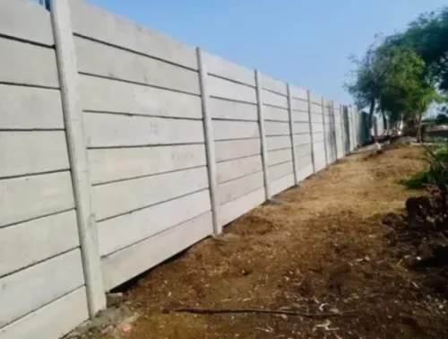
The panel-to-post connection must transfer load without creating a point contact. Out-of-plumb posts, debris in grooves, uneven bearing or hard packing at one location can concentrate the reaction, causing corner spalling or premature cracking. A lighter prestressed panel eases handling, but it also makes accurate posts, joints, foundations and erection controls more important.
Where prestress improves performance—and where design still governs
Prestress places the panel in longitudinal compression before wind or impact creates tension. That compression delays flexural cracking, limits crack width and improves resistance during lifting, transport and installation; it does not make the panel immune to cracking. Impact can still cause local crushing, splitting or breakout at panel ends, lifting holes and post grooves.
A prestressed panel works most efficiently between posts rather than as an unsupported cantilever. For a uniformly distributed lateral load, bending moment rises roughly with the square of the panel span, so increasing post spacing from an economical layout can demand a deeper panel or more prestressing steel.
Prestress losses from shrinkage, creep, steel relaxation and anchorage effects also reduce the compression available in service.
Wind pressure still requires a complete wall calculation. Check:
- Site basic wind speed, exposure, wall height, topography and pressure coefficients
- Solid-wall loading versus the reduced loading of a porous fence
- Panel bending and shear, including support-region bearing and splitting
- Post bending, shear, embedment and connection forces
- Footing overturning, sliding, soil bearing pressure, uplift and socket breakout
The load path remains panel to post, post to footing or grade beam, and foundation to soil. A strong panel cannot correct inadequate post spacing, a weak joint, insufficient embedment or a footing that overturns first. Structural design must therefore combine prestress data with the wall’s geometry, connections, foundation and ground conditions.
Why joints, tolerances, soil and drainage control real-world stability
A prestressed panel can fail at its ends, posts or footing even when its flexural strength is adequate. Out-of-plumb posts, uneven bearing, debris in grooves, or hard packing at one point concentrate bearing stress instead of distributing the reaction; the result can be corner spalling, cracking, or damage during lifting loads.
| Condition | Failure mechanism | Site check |
|---|---|---|
| Misaligned posts | The panel binds at one edge, creating a concentrated reaction and local cracking. | Check post plumb, spacing and groove width before setting each panel. |
| Uneven support | A short bearing length raises local stress and can chip the panel end. | Confirm continuous, level bearing; remove debris and avoid single-point packing. |
| Weak foundation soil | Overturning or sliding occurs before the panel reaches its bending capacity. | Verify soil bearing capacity, footing width, embedment and post-socket resistance. |
| Poor drainage | Water softens surrounding soil and remains at sockets, accelerating corrosion and freeze-thaw damage where applicable. | Provide falls, free-draining backfill and outlets; prevent ponding at the ground line. |
| Inadequate joint clearance | Thermal movement or erection tolerances transfer unwanted force into the panel. | Follow the specified joint gap and seal exposed openings without blocking drainage. |
Design the complete path: panel, connection, post, footing and soil. Check overturning, sliding, uplift where relevant, soil pressure and local failure around each post socket. Prestressing does not compensate for a narrow footing or shallow embedment.
Drainage also protects durability. A crack or damaged end near standing water can admit chlorides, while unsealed exposed steel corrodes; accurate erection and curing remain essential.
What to request when comparing prestressed compound wall systems
Ask for a system design pack, not a panel brochure, when comparing prestressed compound walls. The pack must show the load path from panel to post, post to footing, and footing to soil, with calculations for stated post spacing, embedment, foundation size, soil bearing capacity and connection details.
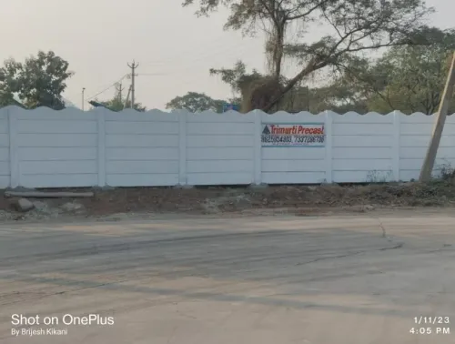
Ask Trimurti Precast to identify these design inputs rather than relying on a standard panel specification.
- Wind design calculation to IS 875 Part 3, including basic wind speed, exposure, wall height, solidity or permeability, pressure coefficients and the resulting load on each panel and post.
- Structural calculation to IS 456 and IS 1343, showing concrete strength, prestressing method, tendon or wire details, transfer strength, losses, crack control, lifting cases and service-load checks.
- Factory quality records showing casting dimensions, curing, concrete test results, tendon stressing records and permitted dimensional tolerances.
- Foundation and erection drawings showing post sections, reinforcement, embedment, footing or grade-beam dimensions, joint gaps, bearing lengths, lifting inserts and temporary supports.
| Document or figure | Compare | What it proves |
|---|---|---|
| Panel schedule | Thickness, span and mass | Whether the panel suits the proposed post spacing |
| Design results | Allowable bending moment and deflection limit | Whether wind and handling demands remain within capacity |
| Post and footing schedule | Section, reinforcement, embedment and soil assumptions | Whether the complete wall can resist overturning |
| Connection detail | Bearing, keys, grout, fasteners and tolerance | Whether forces can actually pass between components |
| QA and handling plan | Lifting orientation and temporary bracing | Whether erection loads are covered, not just final wind loads |
Related products
 | Compound Walls Product Details: Material Concrete,RCC Wall Type Compound Wall Built Type Panel Build, Prefab Thickness 50 mm Width 2 Inches Height 2 Feet - 10 Feet... View product → |
 | Compound Walls Product Details: Minimum Order Quantity 200 Feet Material Concrete Wall Type Compound Wall Thickness 50 mm Built Type Prefab Material Grade M30 Plank... View product → |
Frequently asked questions
What does prestressing change inside a compound wall panel?
It places the concrete under longitudinal compression before service loads arrive, helping counter tensile stress when bending occurs.
How do forces travel from a compound wall into the ground?
Wind or impact loads move through the panel and its connections into posts, foundations and the supporting soil.
What controls real-world stability besides panel strength?
Joints, installation tolerances, soil conditions and drainage determine how reliably the wall transfers loads and resists movement.
What should you request when comparing prestressed compound wall systems?
Request details of the prestressing steel, concrete strength, load design, joint arrangement, tolerances, foundation requirements and quality records.
Related product
 | Compound Walls Product Details: Thickness 50 mm Material RCC, Concrete Built Type Prefab Build, Panel Build Beams Size 6 x 6 Inches, 150 x 150 mm, 200 mm x 200 mm... View product → |