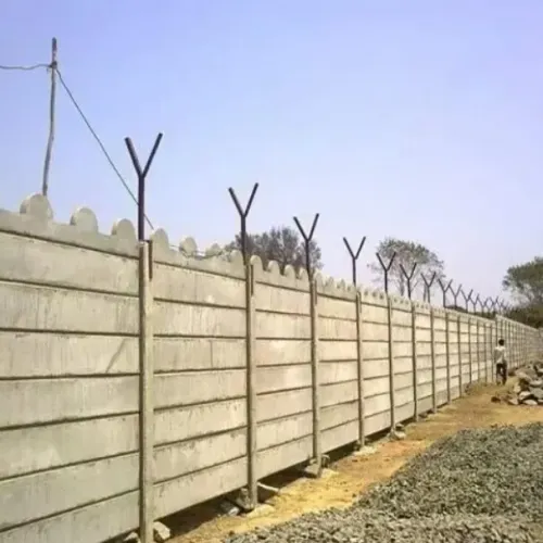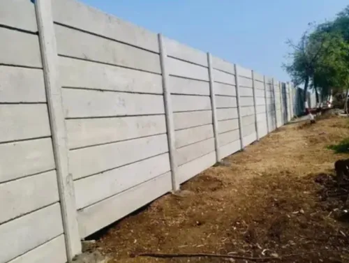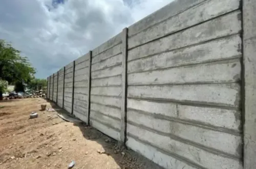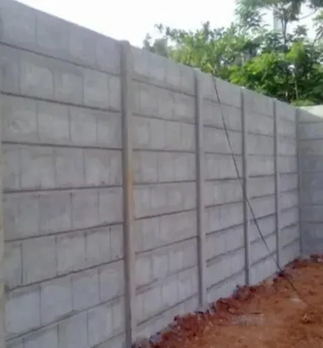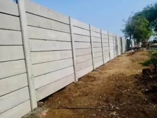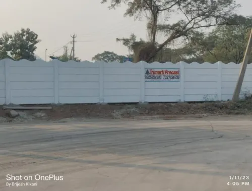
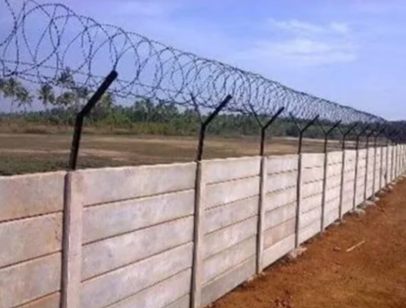
A precast compound wall is installed as a coordinated system, not as a row of panels placed along an existing fence line. Before you order, you need a verified boundary, a site-specific foundation design, a measured component schedule, and a delivery and erection plan that protects the units and the people handling them.
Key takeaways
- Confirm the legal boundary before ordering panels or fixing the fence line.
- Match the foundation and post layout to soil, slopes, drainage, and wall loads.
- Reserve lifting access and sequence deliveries around the installation plan.
- Record unit checks, control joints, backfill, drainage, drawings, and responsibilities.
Survey the Site and Set Out the Wall Before Ordering
A wall can be structurally sound and still be in the wrong place. Complete a site survey and confirm the legal boundary before anyone orders panels; an unverified fence line can create a dispute, demolition, or both.
1. Obtain the boundary plan and have a licensed surveyor locate boundary markers, road reserves, easements, setbacks, and utility corridors. Record property line constraints, neighbouring structures, driveway sight lines, fire access, and gate-swing clearance.
2. Establish a fixed site datum, then take finished-ground levels on both sides at corners, gates, changes in direction, and regular intervals. A level difference changes the design: classify the wall as freestanding or retaining and obtain a retaining-wall design where soil bears against it.
3. Mark the proposed line on the ground with stakes and string, including every corner, offset, curve, step, and change in direction. Check each point against the legal boundary rather than an existing fence, which may be misplaced.
4. Set out gate openings from the actual gate schedule, including clear width, swing, hinges, stops, and vehicle turning space. Mark separate gate-post centres because gate loads require their own reinforcement and foundation design.
5. Measure the final panel bays between post centres and prepare an elevation showing panel heights, solid or patterned units, end posts, corner posts, plinths, and level changes. Do not infer foundation depth, width, or post embedment from panel thickness.
6. Plot overhead and underground services, excavation restrictions, delivery access, lifting positions, and panel storage areas. Approve the signed setting-out drawing before fabrication; changing openings or alignment after production costs far more than revising a drawing.
Choose the Foundation and Component Layout for Actual Site Conditions
A standard post footing is not a safe default for every boundary. Foundation design must follow soil bearing capacity, groundwater, finished-level differences, wall height, wind exposure, and the loads created by gates and corners.
| Ground condition or geometry | Foundation response | Bill of quantities impact |
|---|---|---|
| Natural firm soil | Check individual post footings or a continuous grade beam against overturning and sliding | Posts, excavation, concrete, reinforcement, and formwork |
| Filled ground or soft soil | Obtain geotechnical advice; use redesigned footings, a beam, or deeper support where required | Add soil improvement, extra concrete and steel, disposal, and testing |
| Black-cotton soil | Design for expansive movement and seasonal moisture change; do not copy a standard detail | Include revised embedment, reinforcement, and possible ground treatment |
| Groundwater or wet low points | Provide groundwater drainage and prevent water from collecting around post pockets | Add drains, granular layers, outlets, pumping, and erosion protection |
| Slope or stepped boundary | Use stepped foundations and varied post or panel lengths; check each change in level | Include step details, additional posts, infill panels, and excavation |
| Level difference across the wall | Classify the wall as freestanding or retaining and obtain a retaining-wall design | Add retaining reinforcement, drainage, filters, and stronger foundations |
Treat solid panels, open panels, end posts, corner posts, and gate posts as separate load cases. Gate posts need their own reinforcement and foundations because opening forces and wind loads do not match intermediate posts.
Measure the bill of quantities from the actual geometry: panel lengths, corners, direction changes, offsets, steps, plinths, gate openings, joints, concrete, steel, excavation, drainage, and backfill. Check road setbacks, utility easements, gate swings, sight lines, and vehicle-impact exposure before fabrication.
Plan Delivery, Lifting, and the Installation Sequence
Confirm truck access, crane lifting capacity, ground bearing, and the unloading area before dispatch. The lift plan must state each panel’s mass, lifting anchors, centre of gravity, sling angles, crane radius, exclusion zone, and landing supports.
Use a certified crane, slings, tag lines, spreader beam where specified, survey equipment, excavator, compactor, concrete or grout equipment, and timber dunnage.
Provide a site supervisor, surveyor, crane operator, qualified riggers, installers, and a banksman. Fence the lifting zone and keep people beneath suspended panels out. Prepare adjustable temporary bracing before the first post is lifted; never rely on a loose panel to hold an unrestrained post.
- Mark the approved alignment, corners, direction changes, gate openings, levels, and post centres. Check truck turning space and keep excavated material clear of the lifting route.
- Excavate post pockets and foundation trenches to the designed depth and width. Remove loose or wet material, place reinforcement and concrete or lean base as specified, and verify each pocket’s location.
- Set end, corner, gate, and intermediate posts first. Plumb and align them with a total station, laser, string line, and level; brace every post before placing panels.
- Install panels only after post spacing, line, level, and plumb pass inspection. Lower panels onto designed bearing points without forcing them between posts.
- Complete specified joint seals, grout, coping, and pocket backfill. Keep temporary bracing in place until concrete or grout reaches the specified strength, then remove it and inspect joints, levels, gate clearances, and damage.
Check Delivered Units and Control Joints, Backfill, and Drainage
Quarantine any unit with structural cracks, exposed steel, broken lifting inserts, or major dimensional deviation before installation; transport damage is not automatically a manufacturing defect.
Use this concrete inspection checklist on arrival:
- Compare panel and post dimensions, identification marks, and quantities with the approved schedule.
- Check faces, corners, edges, lifting points, honeycombing, colour variation, and surface finish.
- Record photographs of cracks, chipped edges, reinforcement exposure, and damaged inserts before unloading.
- Stack units on firm, level ground at the manufacturer’s support points, with separators that prevent decorative projections from carrying load.
Install posts to the specified line, spacing, level, and plumb before inserting panels. Never force a panel between incorrectly spaced posts; point contact can chip edges, open joints, and leave bending locked into the wall. Use temporary bracing or the specified post-pocket grouting procedure.
Treat nonstructural edge chips only within the agreed repair limits. A crack, inadequate concrete cover, damaged anchor, or exposed reinforcement needs an engineer’s disposition, not routine putty. Apply joint treatment exactly as detailed: clean the joint, preserve the specified width, and use backer rod or sealant where required.
Do not backfill post pockets until the specified concrete or grout strength and curing period are reached. Place and compact approved fill in controlled layers without striking panels.
Grade finished ground away from footings, keep water out of pockets, and divert roof, road, and drain discharge so it cannot scour the base or wash out fines; weep holes do not make a retaining wall safe.
During the final inspection, verify line, plumb, joint width, repairs, drainage flow, and stable backfill.
Put Design Evidence, Quality Records, and Responsibilities in the Order
Before production, require one coordinated drawing set, written acceptance criteria, a priced bill of quantities, and named responsibility for every approval. Check local boundary height, road-reserve, utility-easement, fire-access, gate-swing, and driveway sight-line constraints before fabrication.
1. Obtain the structural design for the complete system: panels, intermediate, end, corner and gate posts, foundations, joints, and gates. It must state wall height, post spacing, embedment, reinforcement, concrete grade, soil bearing assumptions, wind pressure, overturning, sliding, and vehicle-impact loads where relevant.
Reference IS 456:2000 and IS 15916:2010 where they govern the concrete and precast design.
2. Confirm whether the wall is freestanding or retaining. If ground levels differ, demand a retaining-wall design with drainage details; do not approve ordinary panels for backfill pressure.
3. Request M30 concrete records, including mix or batch details, cube-test results, curing records, reinforcement details, and repair records. Ask Trimurti Precast, or any shortlisted supplier, to identify who signs design approval, fabrication inspection, delivery checks, lifting, installation, grouting, curing, and final handover.
4. Put acceptance limits in writing for dimensions, post spacing, line, level, plumb, joint width, finish, colour variation, cracks, honeycombing, exposed reinforcement, lifting damage, and permitted repairs. Cracks, inadequate cover, or damaged anchors require engineer disposition, not putty.
5. Separate panels, posts, foundations, excavation, reinforcement, concrete or grout, joints, coping, finishes, transport, unloading, craneage, temporary works, demolition, gates, and reinstatement in the bill. A linear-metre rate hides these exclusions. Require the supplier’s inspection reports and a cure-strength release before backfilling or full loading.
Related products
 | Compound Walls Product Details: Minimum Order Quantity 200 Feet Material Concrete Wall Type Compound Wall Thickness 50 mm Built Type Prefab Material Grade M30 Plank... View product → |
 | Compound Walls Material Cement Type Boundary Wall Color White Size 8*10 Wall Height 8 to 10 feet Country of Origin Made in India we Trimurti Precast are the leading... View product → |
Frequently asked questions
What should you confirm before ordering a precast compound wall?
Survey the site, locate the legal boundary, mark levels and corners, and record obstructions, slopes, access limits, and drainage paths before finalising quantities.
How do you choose the foundation for a precast compound wall?
Base the foundation and component layout on soil condition, terrain, wall height, drainage, groundwater, and expected loads. Do not use one footing detail across every site.
How should delivery and lifting be planned?
Check vehicle access, unloading space, lifting equipment, storage areas, panel weights, and the installation sequence before dispatch. Coordinate deliveries so units arrive in the order crews will install them.
What records should accompany a precast wall installation?
Keep approved drawings, boundary and setting-out records, delivery details, unit inspection notes, concrete quality records, installation responsibilities, and evidence of control joints, drainage, and completed backfill.
Related products
 | Compound Walls Material Concrete Built Type Modular, Panel Build Shape Rectangle Surface Finish Rustic Height 6 Feet Wall Thickness 5-20 mm We, Trimurti Cement... View product → |
 | Compound Walls Product Details: Material Concrete,RCC Wall Type Compound Wall Built Type Panel Build, Prefab Thickness 50 mm Width 2 Inches Height 2 Feet - 10 Feet... View product → |
 | Compound Walls Product Details: Thickness 50 mm Material RCC Built Type Prefab Build, Panel Build Beams Size 6 x 6 Inches, 150 x 150 mm, 200 mm x 200 mm Height 2... View product → |
 | Compound Walls Concrete Folding Compound Wall Material Concrete Built Type Modular, Panel Build Shape Rectangle Surface Finish Rustic Height 6 Feet Wall Thickness 5-20 mm We, Trimurti Cement... View product → |