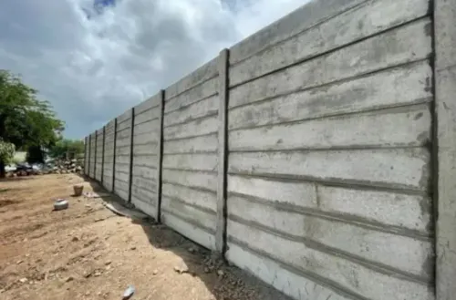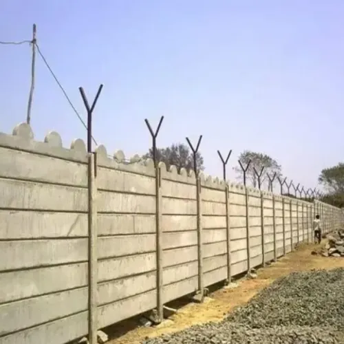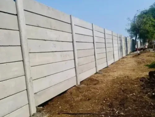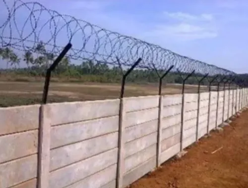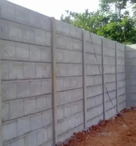
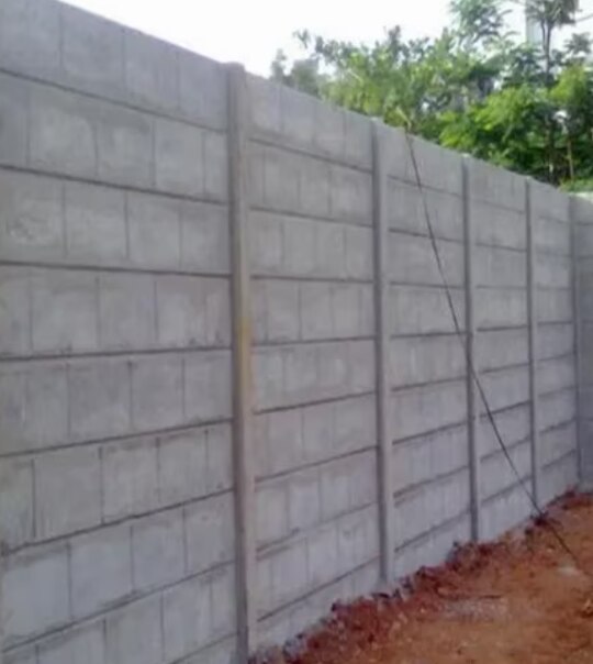
A compound wall must be designed for its ground conditions, wind exposure, connections and foundation—not selected by panel appearance or nominal thickness alone. By the end, you will know which site data, structural documents, concrete specifications and installation checks to require before approving an RCC wall system.
Key takeaways
- Design retaining walls separately from freestanding boundary walls.
- Check soil, wind, impact loads and foundation stability before fabrication.
- Specify concrete cover, reinforcement, curing and joints for durability.
- Require drawings, test reports, delivery checks and installation records.
What must be investigated before designing the wall?
Start by deciding whether the proposed structure is a freestanding boundary wall or a retaining wall. A freestanding compound wall must not be used to hold back soil or resist lateral earth pressure; if ground levels differ, design it as a retaining wall with its own earth-pressure, drainage and stability checks.
1. Confirm the legal line and wall geometry through a boundary survey. Record wall height, corners, gates, openings, changes in level, neighbouring structures and any required offsets before fixing post centres.
2. Identify the soil type and ground variability along the full alignment. Note filled ground, expansive clay, loose sand, rock, soft pockets and evidence of settlement, because isolated post footings suitable for uniform competent soil may fail through bearing loss or differential movement.
3. Establish groundwater levels and seasonal changes, then map drainage paths. Water trapped against panel ends or post sockets can increase pressure, soften soil and accelerate corrosion; provide outlets, granular drainage or stepped foundations where the fall requires them.
4. Use a slope stability assessment (SSA) — a site review of slope movement and drainage risks — where the site slopes, has a cut edge or shows cracking. The project engineer must set the SSA scope and decide whether deeper investigation or slope restraint is necessary.
5. Locate existing foundations, buried services, paving and property structures before excavation. Confirm delivery access and lifting access, including space for the vehicle, crane, spreader and safe panel staging on level, aligned bearers.
How should loads and foundations be checked?
Check the wall as a connected system: each action must travel from panel to post, through the panel-to-post connection, into the pedestal, and finally into the footing and surrounding soil. Design the structure for wind pressure under IS 875 Part 3, not merely for panel self-weight.
- Panel: verify unit mass, wind area, lifting effects and the panel’s bearing on the post or support.
- Post and connection: check bending, shear, anchorage, joint movement and local edge damage. Include gate loads and gate-post actions separately from ordinary wall loading.
- Pedestal: specify pedestal dimensions, reinforcement, concrete strength and post embedment so forces enter the footing without splitting or punching.
- Footing: check overturning, sliding, uplift, bearing capacity, settlement and soil resistance for each load combination.
Include an impact load where vehicles, equipment or public access could strike the wall. Apply seismic actions under IS 1893 Part 1 when the site and structure fall within its scope; a heavy panel increases inertial force as well as foundation demand.
Select an isolated footing on competent, uniform soil only after these checks. Weak fill, expansive soil, slopes or variable ground may require a continuous footing or grade beam, deeper embedment and drainage measures.
Design corners, ends and gate openings for load concentration, and check progressive collapse so failure of one panel or post does not pull down adjacent units.
Which concrete and reinforcement requirements control durability?
Durability is controlled by exposure, permeability, cover and reinforcement detailing, not by concrete grade alone. Apply IS 456:2000 and record the specified compressive strength, water-cement ratio, cementitious materials, aggregate size and exposure class for each panel, post, beam and footing.
| Exposure | Minimum grade | Maximum water-cement ratio | Nominal cover |
|---|---|---|---|
| Mild | M20 | 0.55 | 20 mm |
| Moderate | M25 | 0.50 | 30 mm |
| Severe | M30 | 0.45 | 45 mm |
| Very severe | M35 | 0.45 | 50 mm |
| Extreme | M40 | 0.40 | 75 mm |
Measure nominal cover to the outermost reinforcement and use spacers to keep it continuous. For thin panels, check aggregate size against member thickness and clear bar spacing; oversized aggregate creates honeycombing around edges, mesh and lifting inserts.
Require these documents before production:
- A mix design identifying factory-cast concrete or site-mixed concrete, grade, water-cement ratio, aggregate size, cement type, admixtures and test results.
- An IS 1786 reinforcement certificate, bar schedule and drawings showing mesh, bar arrangement, lap length, anchorage and connection reinforcement for every member.
- An IS 2502-compliant bending and placing schedule, rather than accepting a generic bar detail as universal compliance.
- The design nominal cover, curing period and lifting-strength requirement. IS 456 requires at least seven days’ curing for ordinary Portland cement concrete and ten days with blended cement or mineral admixtures; hot, dry conditions call for fourteen days.
- The corrosion protection specification for reinforcement, inserts and exposed connections where chloride, industrial or sulfate exposure exists.
How should panels, posts and joints be installed?
Install each unit to a surveyed line, not by forcing it into place. Set post spacing, foundation position, joint width, panel seating depth, plumbness, line and level, panel bow, and each construction tolerance before delivery. Record dimensions with a level, laser or gauges; cumulative survey errors can preload panels, chip edges and damage connections.
Lift panels only from designated lifting inserts, using the specified sling angle and spreader arrangement. Support them only at approved points and stack them on aligned bearers on level ground. Arbitrary corner supports or lifting below the specified handling strength can create flexural cracks even when 28-day concrete strength is adequate.
Select the joint treatment according to its structural function:
- Use a dry bearing detail where units transfer compression directly and movement must not be locked by mortar.
- Use dowels and non-shrink grout where the engineered connection must transfer shear or secure the panel to the post; do not substitute ordinary mortar for a movement joint.
- Install an elastomeric seal against water ingress where the joint must remain weather-tight.
- Place compressible filler where thermal, foundation or erection movement requires a controlled gap; keep the specified joint width uniform.
Finish post sockets without blocking drainage outlets. On sloping sites, use stepped foundations and provide a drainage path so water cannot collect against panel ends or inside sockets. Check seating, joint width and plumbness after grouting, then inspect for rattling, forced fits and cracked edges before backfilling.
What documents and inspections should you require from a precast supplier?
Require a signed procurement pack and acceptance plan before ordering; do not accept panels because their nominal length and height match. The supplier must own the engineered system, not merely deliver concrete pieces.
1. Record whether each unit is an infill-only panel or structural panel, its panel thickness classification, panel capacity, concrete grade, unit mass, reinforcement size and spacing, bar schedule, lifting points, permitted support points, post embedment, joint width, dimensional tolerances and tested wind resistance. Obtain design drawings showing the complete load path and foundation reactions.
2. Demand a strength schedule naming release strength, lifting strength, transport strength and installation strength, plus the test method and permitted lifting configuration. Inspect inserts, embedded plates and corner reinforcement; lift only from designated lifting points using the stated sling angle and spreader.
3. Tie every cube test to its batch and pour. Require IS 456 15 m³ sampling: three cubes per sample, with at least one sample for each 15 m³ or part thereof, and acceptance against characteristic strength rather than one favourable result.
Check curing records: seven days for OPC, ten for blended cement or admixtures, and fourteen in hot, dry conditions.
4. Match concrete grade to exposure: M20 mild, M25 moderate, M30 severe, M35 very severe and M40 extreme. At delivery, check thickness, length, squareness, cracks, damage and unit mass against the drawings; reject unapproved substitutions.
Trimurti Precast, like any supplier, should state in writing who designs and warrants panels, posts, connections, lifting, installation and wind performance as one engineered system.
Related products
 | Compound Walls Rcc Folding Concrete Compound Wall Product Details: Wall Type Compound Wall Thickness 50 mm Material RCC Built Type Prefab Build, Panel Build Beams Size 6 x 6 Inches, 150 x 150 mm, 200... View product → |
 | Compound Walls Product Details: Thickness 50 mm Material RCC Built Type Prefab Build, Panel Build Beams Size 6 x 6 Inches, 150 x 150 mm, 200 mm x 200 mm Height 2... View product → |
Frequently asked questions
What must you investigate before designing an RCC compound wall?
Confirm whether the wall is freestanding or retaining, then investigate site levels, soil conditions, drainage, wind exposure, boundary constraints and underground services.
How should RCC compound wall loads and foundations be checked?
Check wind, panel weight, impact and any gate loads, then verify post bending, footing bearing, sliding, overturning, settlement and embedment depth.
Which concrete and reinforcement details control durability?
Specify concrete strength, maximum water-cement ratio, reinforcement grade, concrete cover, compaction, curing and protection against water ingress and corrosion.
What documents should you require from a precast RCC wall supplier?
Request approved drawings, panel and post dimensions, concrete mix details, reinforcement schedules, cube test reports, lifting instructions, delivery records and installation inspection records.
Related products
 | Compound Walls Product Details: Material Concrete,RCC Wall Type Compound Wall Built Type Panel Build, Prefab Thickness 50 mm Width 2 Inches Height 2 Feet - 10 Feet... View product → |
 | Compound Walls Product Details: Material RCC Built Type Prefab Build, Panel Build Plank Length 7 Ft Width 2 Inches Beams Size 6x6 Inches, 150x150 mm, 200 mm x 200... View product → |
 | Boundary Walls Material Concrete Type Prestressed Color Grey Beam Size 6 x 6 Inches, 150x150 mm, 200 mm x 200 mm Size 6 feet Country of Origin Made in India we... View product → |
 | Compound Walls Material Concrete Built Type Modular, Panel Build Shape Rectangle Surface Finish Rustic Height 6 Feet Wall Thickness 5-20 mm We, Trimurti Cement... View product → |